FIRMWARE UPLOAD EMONWRT2: Difference between revisions
(Created page with "Upload emontx Arduino sketch to the EmonWRT ==Required Equipment== * 1 screw driver * 1 FTDI/USB adaptor * A computer running the Arduino IDE ==Steps== 1/ Open the EMonWRT...") |
(→Steps) |
||
| (3 intermediate revisions by the same user not shown) | |||
| Line 1: | Line 1: | ||
Upload | Upload Arduino sketch to the EmonWRT2 | ||
==Required Equipment== | ==Required Equipment== | ||
* 1 screw driver | * 1 screw driver | ||
* 1 | * 1 avr Programmer | ||
* A computer running the Arduino IDE | * A computer running the Arduino IDE | ||
==Steps== | ==Steps== | ||
[[File:IMG_0905_small.png | right]] | |||
1/ Disconnect all cables (ethernet power sensors) from the unit. | |||
2/ Open the EmonWRT2 enclosure removing the four screws. | |||
3/ Download and install the Arduino IDE on your computer. https://www.arduino.cc/en/Main/Software | |||
4/ Open the sketch template given on the main EmonWRT2 page. | |||
5/ | 5/ Modify it to your needs. The main parameters to change are at the top of the sketch. | ||
#define POLLING_INTERVAL 5000 | |||
const float ICAL = 83.33; | |||
const double VCAL1 = 273.9; | |||
const double VCAL2 = 269.5; | |||
const double VCAL3 = 271.0; | |||
boolean THREEPHASE = true; | |||
ICAL is the calibration value for the SCT. VCAL are the calibration value for the Voltage sensor. THREPHASE true or false will enable/disable 3 phase output. | |||
6/ Install all required libraries: | |||
One Wire<br> | |||
http://www.pjrc.com/teensy/td_libs_OneWire.html<br> | |||
arduino-tiny core: <br> | |||
http://code.google.com/p/arduino-tiny/<br> | |||
sendonlySoftwareSerial:<br> | |||
http://lechacal.com/RPICT/7CT1V/SendOnlySoftwareSerial.zip<br> | |||
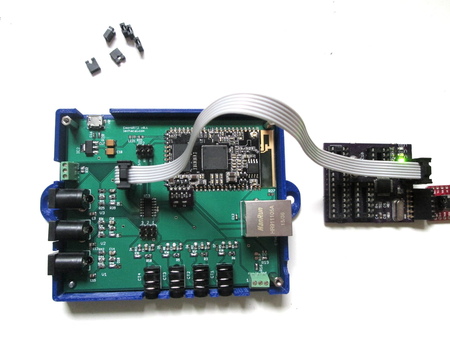
7/ <b>Remove all 6 jumpers from the EmonWRT2 board</b>. | |||
8/ Connect the AVR programmer to the EmonWRT2 board on the FTDI port. Make sure grounds are connected together. | |||
9/ Setup correct serial port and programmer on Arduino IDE. Also make sure that the <b>ATtiny84 @ 8Mhz</b> is selected. | |||
10/ Upload the firmware. Disconnect the avr programmer. Re-install the jumpers. Apply power to the board for testing. | |||
Latest revision as of 17:55, 25 July 2016
Upload Arduino sketch to the EmonWRT2
Required Equipment
- 1 screw driver
- 1 avr Programmer
- A computer running the Arduino IDE
Steps

1/ Disconnect all cables (ethernet power sensors) from the unit.
2/ Open the EmonWRT2 enclosure removing the four screws.
3/ Download and install the Arduino IDE on your computer. https://www.arduino.cc/en/Main/Software
4/ Open the sketch template given on the main EmonWRT2 page.
5/ Modify it to your needs. The main parameters to change are at the top of the sketch.
#define POLLING_INTERVAL 5000
const float ICAL = 83.33;
const double VCAL1 = 273.9;
const double VCAL2 = 269.5;
const double VCAL3 = 271.0;
boolean THREEPHASE = true;
ICAL is the calibration value for the SCT. VCAL are the calibration value for the Voltage sensor. THREPHASE true or false will enable/disable 3 phase output.
6/ Install all required libraries:
One Wire
http://www.pjrc.com/teensy/td_libs_OneWire.html
arduino-tiny core:
http://code.google.com/p/arduino-tiny/
sendonlySoftwareSerial:
http://lechacal.com/RPICT/7CT1V/SendOnlySoftwareSerial.zip
7/ Remove all 6 jumpers from the EmonWRT2 board.
8/ Connect the AVR programmer to the EmonWRT2 board on the FTDI port. Make sure grounds are connected together.
9/ Setup correct serial port and programmer on Arduino IDE. Also make sure that the ATtiny84 @ 8Mhz is selected.
10/ Upload the firmware. Disconnect the avr programmer. Re-install the jumpers. Apply power to the board for testing.