RPI LCT4V3: Difference between revisions
(→Sketch) |
|||
| Line 106: | Line 106: | ||
[[File:Emoncms_channels.png]] | [[File:Emoncms_channels.png]] | ||
== | ==Files== | ||
===Default Sketch=== | |||
[http://lechacal.com/RPICT/7CT1V/RPICT7V1_v2_5.ino Default Sketch V2.5.]<br> | |||
[http://lechacal.com/RPICT/ | [http://lechacal.com/RPICT/7CT1V/RPICT7V1_v2_6_3.ino Default Sketch V2.6.]<br> | ||
[http://lechacal.com/RPICT/7CT1V/RPICT7V1_v2_7_1.ino Default Sketch V2.7.1.]<br> | |||
[http://lechacal.com/RPICT/ | |||
[http://lechacal.com/RPICT/7CT1V/RPICT7V1_v2_8_0.ino Default Sketch V2.8.0.]<br> | |||
<small>(note boards are sold already flashed with latest firmware).</small> | |||
===noOSC Sketch=== | |||
The Default sketch allows up to 28 computation nodes to be run. If more are needed for higher stacks then we recommend to use the noOSC sketch. This is the same as the default sketch but Over Serial Configuration (OSC) as been removed to allow up to 40 nodes to be computed. Configuration has to be edited in the sketch. | |||
[http://lechacal.com/RPICT/7CT1V/RPICT_noOSC_v1_0.ino noOSC Sketch v1.0]<br> | |||
[http://lechacal.com/RPICT/7CT1V/RPICT_noOSC_v1_1.ino noOSC Sketch v1.1]<br> | |||
[[File:IMG_1236_small.png | 350px]] | |||
==Related Pages== | ==Related Pages== | ||
Revision as of 17:06, 18 January 2019

This page is for board specific information. More information can be found on the generic page for RPICT series.
The RPI LCT3V1 has been specifically designed for large CT of 400A and more. CT connector are screw terminal types as opposed to jack connectors.
- 4 AC current sensor
- 3 AC Voltage sensor.
- Compute real power.
- Fit on Raspberrypi 2 holes mounting pattern.
- Attiny84 Mcu
- Use with 400A CT
Compatibility
| Version | Compatible? |
|---|---|
| Raspberrypi 1 A | Yes |
| Raspberrypi 1 B+ | Yes |
| Raspberrypi 2 B | Yes |
| Raspberrypi 3 B | Yes |
| Raspberrypi 3 B+ | Yes |
The RPI_LCT4V3 is not stackable.
Recommended sensors

- AC Current sensor: SCT-024
- AC Voltage sensor:
- UK: 77DB-06-09
- EU: 77DE-06-09
- US: 77DA-10-09
Configuration

See general instructions for configuration below:
Over Serial Configuration - Sketch 2.8
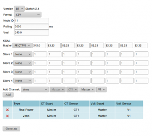 Starting from sketch 2.4 the board can be configured with the online configurator.
View the data with Python
Please note the configuration must have Emonhub format enabled (format=3). The example script below will be a good starting point.
First of all make sure you have python-serial package installed
$ sudo apt-get install python-serial
Then copy the following into an executable file and run it.
#!/usr/bin/python
import serial
ser = serial.Serial('/dev/ttyAMA0', 38400)

try:
       while 1:
               response = ser.readline()
               z = response.split(" ")
               if len(z)>=7:
                       print "Vrms 1: %s Volt" % z[1]
                       print "Vrms 2: %s Volt" % z[2]
                       print "Vrms 3: %s Volt" % z[3]
                       print "RealP 1: %s Watt" % z[4]
                       print "RealP 2: %s Watt" % z[5]
                       print "RealP 3: %s Watt" % z[6]
                       print "RealP 4: %s Watt" % z[7][:-2]
except KeyboardInterrupt:
       ser.close()
Emoncms Config (Emonhub)
For default configuration.
 [[11]]
   nodename = my_RPI_LCT4V3
   hardware = RPI_LCT4V3
   [[[rx]]]
      names = Vrms1, Vrms2, Vrms3, RP1, RP2, RP3, RP4
      datacode = 0
      scales = 1,1,1,1,1,1,1
      units = V,V,V,W,W,W,W
Using the default sketch the output will be
NodeID Vrms1 Vrms2 Vrms3 RealPower1 RealPower2 RealPower3 RealPower4
- RealPower in Watts
- Vrms in Volts

Files
Default Sketch
(note boards are sold already flashed with latest firmware).
noOSC Sketch
The Default sketch allows up to 28 computation nodes to be run. If more are needed for higher stacks then we recommend to use the noOSC sketch. This is the same as the default sketch but Over Serial Configuration (OSC) as been removed to allow up to 40 nodes to be computed. Configuration has to be edited in the sketch.
noOSC Sketch v1.0
noOSC Sketch v1.1

Related Pages
How to calibrate the Voltage Port